How to Replace Front Lower Control Arm 1998-2011 Ford Ranger
Created on: 2016-12-14
Find out how to remove the torsion bar and sway bar links to access and replace the front lower control arm with a ball joint on the 98-11 Ford Ranger
-
step 1 :Removing the Wheel
- Pry off the center cap with a flat blade screwdriver
- Remove the wheel lock lug nut with a wheel lock key
- Loosen the 19mm lug nuts with the vehicle on the ground
- Raise the vehicle with a floor jack
- Secure the vehicle on jack stands
- Remove the lug nuts
- Pull off the wheel
-
step 2 :Removing the Torsion Key Cover
- Mark an index where the torsion bar enters the front lower control arm
- Mark an index where the key meets the backside of the bar
- Count the number of turns it takes to remove the middle 13mm tensioner bolt
- Remove the four 13mm bolts from the key cover
-
step 3 :Removing the Torsion Key
- Set a two jaw puller into both side of the crossmember
- Install the forcing screw into the divet on the torsion key
- Add tension with a socket and breaker bar to move the key off of the keeper
- Slide the keeper out of the crossmember
- Loosen the two jaw puller to release tension from the key
- Tap the key off of the end of the torsion bar with a hammer
-
step 4 :Removing the Torsion Bar
- Hit and release the torsion bar from the lower control arm with a hammer
- Remove the torsion bar from the control arm
-
step 5 :Removing the Sway Bar Links
- Remove the lower bolt with a 16mm wrench and 18mm socket and ratchet
- Loosen the bottom washers and bushings
- Clip the bottom part of the link with pliers
- Thread a nut on the bottom
- Loosen the top bolt white hammer the sway bar up and out of the control arm
-
step 6 :Removing the Front Lower Control Arm
- Remove the two 13mm nuts on the bottom of the control arm
- Straighten out the cotter pin with needle nose pliers
- Remove the ball joint castle nut with a 24mm socket and ratchet
- Tap the side of the control arm to tap the ball joint out, or use a pickle fork
- Break the back control arm bolts loose with a 21mm socket and breaker bar
- Remove the bolts with the captured nut in the frame if possible
- Pull the control arm out of the frame
- Remove the control arm
-
step 7 :Installing the Front Lower Control Arm
- Remove the new castle nut
- Flip the control arm over
- Insert the grease fitting into the ball joint
- Tighten the grease fitting with an 8mm wrench
- Insert the lower ball joint into the spindle
- Start the castle nut on by hand
- Apply brake grease to the face of the bushings, sleeve, and inside the sleeve
- Apply brake grease inside the torsion bar slot
- Install the control arm into the frame
- Insert the back control arm bolts into place and tighten them preliminarily, not all the way
- Tighten the 27mm ball joint nut
- Torque the ball joint nut to 98 foot-pounds
- Install the cotter pin and bend the ends
- Line the shock into the control arm
- Install the 10mm bolts and tighten them with a 10mm wrench and 13mm socket and ratchet
-
step 8 :Installing the Front Sway Bar Links
- Coat the bolt with anti-seize grease or lubricant
- Insert a washer and bushing onto the bottom
- Insert the bolt into the way bar
- Insert a bushing and washer onto the bottom
- Insert the sleeve onto the bar
- Insert a washer and bushing onto the bottom
- Insert the bolt into the control arm
- Replace the bar for the other side
- Insert a bushing and washer onto the bottom
- Pry down on the sway bar to compress the bushings
- Insert a 16mm socket and ratchet on top
- Insert 18mm wrench on the bottom
- Tighten the sway bar link to compress the bushings tightly
- Tighten the other side
-
step 9 :Installing the Torsion Bar
- Insert the torsion bar into the control arm
-
step 10 :Installing the Torsion Key
- Insert the torsion key to the torsion bar
- Set a two jaw puller into both side of the crossmember
- Install the forcing screw into the divet on the torsion key
- Add tension with a socket and breaker bar to move the key up
- Insert the adjustor block into the crossmember and below the key
- Loosen the tension to lower the torsion key onto the adjustor block
- Remove the two jaw puller
-
step 11 :Reinstalling the Torsion Key Cover
- Reinstall the cover and the four 13mm bolts
- Hand-tighten the adjusting bolt until it touches the bottom of the torsion key
- Tighten the adjusting bolt back to the number of turns used to remove it
-
step 12 :Reattaching the Wheel
- Slide the wheel into place
- Start the lug nuts by hand
- Tighten the lug nuts preliminarily
- Lower the vehicle to the ground
- Tighten the lug nuts to 100 foot-pounds of torque in a crossing or star pattern
- Reattach the center cap
Tools needed
-
Socket Extensions
Torque Wrench
16mm Wrench
Hammer
Rust Penetrant
Channel-Lock Pliers
Pry Bar
Jack Stands
Safety Glasses
2 Jaw Gear Puller
Pick
Gloves
Flat Blade Screwdriver
Anti-Seize Grease
Chisel
Ratchet
Floor Jack
Needle nose pliers
1/2 Inch Breaker Bar
Marker / Writing Utensil
Complete Metric Socket Set
Hi, I'm Mike from 1AAuto. We've been selling auto parts for over 30 years! We're dedicated to delivering quality auto parts, expert customer service, and fast and free shipping, all backed by our 100% satisfaction guarantee. So visit us at 1AAuto.com, your trusted source for quality auto parts.
In this video, we're going to be working with our 2001 Ford Ranger four-wheel drive. We're going to show you how to remove and replace your front lower control arm. This procedure does involve working with some special tools and some high tension parts, so please make sure that you are properly equipped and confident in making this repair before starting this procedure.
If you like this video, please click subscribe. We have a ton more information on this truck, as well as many other makes and models. If you need this part for your vehicle, you can follow the link down in the description over to 1AAuto.com.
Here are the items you'll need for this repair: 8-27mm sockets, wrench, ratchet, socket extension, breaker bar, torque wrench, pry bar, pickle fork, hammer, two jaw puller, flat punch, wide chisel, pliers, needle nose pliers, brake grease, rust penetrant, marker, flat blade screwdriver, safety glasses, gloves, jack, jack stands
Using a flat blade screwdriver, remove the center cap from your wheel. Using a 19 millimeter socket and breaker bar, loosen your lug nuts one turn. We have a wheel lock on ours, so we'll be using a wheel lock key to remove it. Raise and support your vehicle. We're using a lift, but this job can easily be done in the driveway with a jack and jack stands. Finish removing your lug nuts by hand. Remove your wheel and tire from the vehicle.
Your torsion bar is the spring suspension for the front end of the vehicle. We're going to index where it goes in to our lower control arm here, just to make sure that everything goes back in the same way it came out. Now we know to make this side of the arm match there. At the rear of the torsion bar is what's called the torsion key, which this bolt tightens and loosens that key to add more or less tension to the bar. We'll index the key to the backside of the bar as well, just to make sure everything goes together the same. This 13 millimeter bolt and this access panel here is what tensions the key for the torsion. What we're going to do is make sure we count the number of rotations to remove it so we can install it the same number of turns. 1, 2, 3, 4, 5, 6, 7, 8, 9, 10, 11, 12, 13, 14, 15, 16, 17, 18 turns. Remove this cover with the two 13 millimeter bolts at the top, and two more at the bottom. Be sure to hold on to this cover when you remove the last bolt.
Removing the keeper from the torsion bar and key is a high-tension and a potentially dangerous procedure, so be sure to wear proper safety equipment during this step. This divot in the torsion key is designed to have a two jaw puller set into it. Set the jaws on both sides of the cross member, and install the forcing screw into the divot. Using the appropriate sized socket for your particular two jaw puller and a breaker bar, add tension until this keeper can be removed. Once the key has been moved up and off of the keeper, lift up and slide the keeper out of your cross member. Then, carefully loosen the two jaw puller until all of the tension is off of the key. Now that the tension is off of your bar, you can tap the key off of the end of your torsion bar with a hammer. We soaked our torsion key in penetrating oil. Now we're going to pry it down with a pry bar, tap it loose. You have this little cover up here that we can pull down, and then remove the key from the torsion bar, and remove our pry bar. Using a large hammer, hit the torsion bar and release it from the lower control arm.
Now that we've hit the control arm to break some of the rust loose, and you may just be able to grab this torsion bar and remove it by hand, but ours is rusted in there. We're going to use a large punch and a big hammer and try and tap the torsion bar free from the control arm. Now our torsion bar is kind of an extreme situation. Normally, you should just be able to pull these out of the back of the control arm by hand, but ours is rusted and really seized in there. You can't use heat, or you can't use a lot of heat on a torsion bar, because it's spring steel, and heating it up will make it loose its spring quality, and cause you to have to replace both of the torsion bars.
What we're going to do, since we're replacing our lower control arm anyway, is cut a section out of the lower control arm here to try to relieve the pressure inside of the sleeve from all the rust build up. We're going to be using an air grinder, or an air cut off wheel. You could also use an electric cut off wheel, grinder, or if you had to, a sawzall would get the job done eventually. Be sure to use proper safety equipment and all the proper safety precautions, especially if you're doing this on a jack and jack stands to make sure that you can free this safely.
Be sure to score along the metal, making shallow marks and getting deeper so you cut through clean and even, because going too far is going to damage our torsion bar and cause us to have to replace it. What you can see I've done here is cut through the thicker ends first, and then we're making a long score along the center. I'm working this back and forth through the channel, because cutting into one section all the way through and trying to walk across could cause us to over cut, and will also chew through these cut off blades much, much faster. Going back and forth through the score on thick metal is a good way to cut through clean and efficient without chewing through your cut off wheels. Now that we've cut all the way through, we're going to use a wide chisel to try to hammer in there and spread out the socket that's holding our torsion bar in place.
Another method we can try is using an air chisel to try to separate this if we can't get a hand chisel in. With our chisel wedged in there, spread the control arm. We'll use a piece of pipe, or you can use a large deep well socket, like an axle nut socket, and tap it with a hammer to try to free that torsion bar. Once it's been loosened up enough, remove it from the control arm.
Remove your sway bar link. Ours is an aftermarket replacement, so our sizes may vary from yours, but we need a 16 millimeter wrench on top, and an 18 millimeter deep socket and ratchet on the bottom. Remove the nut, as well as the bottom washer and bushing. These may require some prying off. You may be able to grab that washer with a pair of pliers, and the bushing, and just work them off the bottom. Now, we'll reinstall the bottom bolt just until it sits flush with the bottom of the threads, this way we don't damage them. Once they're on there flush, we'll work the bolt on the top while tapping this nut until it's free. All we want to do is work that bolt up out of the lower control arm. If we go much farther than that, there's a risk of the rest of the sway bar link falling apart, and that just makes it more difficult for us to reinstall later.
Remove the two 13 millimeter nuts on the bottom of the control arm for the shock absorber. You may have to counter hold the bolt going through the top of the control arm. Remove the bolt once the nut is out, and repeat this step for the opposite bolt. Now we'll use a pair of needle-nose pliers to straighten out the cotter pin in our lower ball joint. Our lower ball joint nut is a 24 millimeter socket. We still have a chunk of the cotter pin in there, but it's so old and rusty, and since we're replacing this anyway, we can probably get the nut to rotate right around it and snap it off.
We will have to tap our 24 on with a hammer, and then break it off with a half inch extension and breaker bar. For really stubborn hardware, you may need a cheater pipe for some extra leverage. Now we'll hit the side of the control arm to try to get the ball joint to pop out. Where our new control arms comes with the lower ball joint, you may try using a pickle fork if the first method doesn't work. We may not be able to fully remove this until we've released the rear of our control arm.
Using a 21 millimeter socket, break the control arm bolts loose with a breaker bar. The nut on the back is secured into the frame, so as long as that little wing on it doesn't break, we shouldn't have to support the other side with a ratchet. Once we've broken it loose, we'll switch over to a ratchet. Once our bolt is free, we'll remove it from the control arm and leave our captured nut hanging in the frame if possible. When removing the last control arm bolt, be sure to support the control arm so it doesn't fall out on you. Then we'll pull it down out of the frame. With the control arm loose, we should be able to remove our lower control arm without the need to remove our CV axle.
Here we have our old control arm that we removed from our vehicle, and our new part from 1AAuto.com. As you can see, these parts are exactly the same shape. We have the same mounting holes for our shock, as well as our sway bar link. We have a brand new lower ball joint in our new control arm, which actually comes with an opening with a new grease fitting, a new cotter pin, and it's even got a brand new nut on the bottom. You can see our old ball joint here has a lot of play in it, that was no good, as well as our bushings are a little torn and deteriorated, pretty beat up. Those are going to make some noises and cause some odd handling characteristics.
Fortunately, our new control arm comes with a brand new set of bushings in it too. Now, all these parts are capable of being changed individually. You could keep your old control arm and change out your bushings and your ball joint, but that adds a lot of work and down time to your vehicle, and, in some extreme cases, like ours, you have to cut through it to actually get that torsion bar out of there. Replacing this whole assembly saves you time, replaces all of the critical wear items in the lower control arm, gets your vehicle handling right, and quiets down that noisy suspension. Plus, it's direct fit, just like our original equipment, and it's going to fix you up right.
Remove the new castle nut from our lower ball joint. Flip it over and install your grease fitting. This simply threads in. We'll tighten that down with an 8 millimeter wrench. You really don't need to go super, super tight on these, but you do want to make sure it gets in there nice and snug so no grease leaks out past it. Start by installing the lower ball joint back into the control arm. It's pretty tight, so you are just going to have to work it around until you find the right angle to get it in there. Once you've got the ball joint set into place, start the nut on by hand. This will just make sure we don't have it move or potentially fall out on us while we set everything else up.
Now to combat the rust problem that we clearly had when removing these, we're going to take some grease, you can use a brake grease, or you can use an anti-seize grease, just going to grease up the fact of that bushing, as well as the sleeve and the inside of it. This will keep the bushings from seizing and squeaking against the body, as well as keeping the bolt from seizing into that collar. We'll do the key way for or torsion bar as well to prevent that from getting bound in there and having to be cut out like our last one. Make sure we get this through and through on both sides of both bushings and into both bushing sleeves. This will make installation easier, and should we ever have to remove or replace these parts again in our vehicle's lifetime, it'll be that much easier the next time around.
Reinstall the control arm bushings into the frame. Now this step is crucial. When installing these bolts, we do not want to tighten them up all the way until the weight of the vehicle is back on to our suspension. That way our bushings are nice and straight when they're tight at the vehicle's normal ride height, meaning they have their full range of motion in both directions, with no pre-load to cause premature bushing wear. Now it is all right to bring the bolts down close, but again, do not tighten them. Tighten down the ball joint nut. Our new one is 27 millimeters. Torque the ball joint nut to 98 foot-pounds.
Install the cotter pin through the slots in the castle nut and the opening in the ball joint. Pull it through. I like to fold these down and over the nut. Trim this one. Or, some people like to put it in sideways and turn both legs around the nut. I find this method to be simpler to remove and a little bit stronger at holding everything in place.
Line up the shock. This may require you to lift up on the suspension. Install the first bolt and start the first nut by hand. This will keep everything aligned while we install the other bolt and nut. With both nuts and bolts in place, we'll secure the top of the bolt with our 10 millimeter wrench, and tighten down the nut with a 13 millimeter socket and ratchet. Now, our sway bar fell out during this procedure, so to reinstall it, we'll put the bolt through with a washer and a bushing on the top. Then, we have a bushing and a washer go up and against the bottom, followed by our sleeve, followed by a washer and then a bushing. That'll go into our lower control arm. Pry up on the sway bar and reinstall the bolt through the washer and bushing, and into the lower control arm. We'll then place our final bushing, then washer, onto the threads, followed by our nut, which we will then tighten down with a 16 millimeter wrench atop the bolt, and an 18 millimeter socket and ratchet on the bottom.
We've transferred our indexing mark onto the socket of our new control arm, which will line up the mark on our torsion bar too. Simply slides in. Line up your indexing marks and reinstall your torsion key onto the other end of the bar. Reinstall the two jaw puller into the divot on your torsion key. Again, make sure it's on there nice and secure. Use your proper safety equipment and a 16 millimeter socket and ratchet. For our particular puller, run that torsion key up until we can get our adjuster block back through the cross member. Once it's through, reinstall the adjuster block and its channels into the cross member, and carefully lower the torsion key back onto it.
Reinstall the cover and the three 13 millimeter bolts. Tighten the bolts down with a 13 millimeter socket and ratchet. Get the bolt in by hand for your adjuster block, just until it touches the bottom of your torsion key, at which point we use that 13 millimeter socket and ratchet to install the exact same number of turns we used to remove it.
Reinstall your wheel and tire onto the hub. Get your lug nuts on as tight as you can with the wheel in the air. Put the weight of the vehicle back onto the tires. Now we'll torque our lug nuts to a hundred foot-pounds in a cross pattern, making sure you end with your locking wheel lug if you have one. Again, these are a 19 millimeter. Line up the tabs on your center cap and place them over the lug nuts, and tap it into place. With the weight of the vehicle back on the suspension, we can now finish torquing or lower control arm bolts to 121 foot-pounds. Repeat this step on the rear bolt to torque, and you're good to go.
Thanks for watching. Visit us at 1AAuto.com for quality auto parts, fast and free shipping, and the best customer service in the industry.
Shop Products


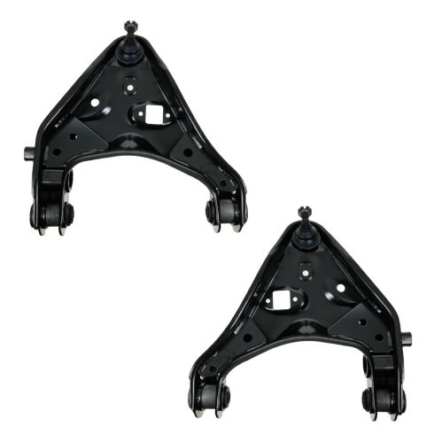
Ford Mazda Mercury Front Driver & Passenger Side 2 Piece Control Arm with Ball Joint Set TRQ PSA62153
Part Details:
- 2 Piece
- (1) Front Driver Side Lower Control Arm with Ball Joint
- (1) Front Passenger Side Lower Control Arm with Ball Joint

How to Replace Passenger Side Lower Control Arm 2007-14 Ford Edge
Control arms are a crucial part of the suspension system of your vehicle. They carry the load of the vehicle to the wheel and maintain its alignment. Control arms are large and strong. They contain rubber bushings for smoother rides at the cost of eventual wear. How to install a new quality TRQ passenger side lower control arm in your 2007-14 Ford Edge.
