How to Replace Front Struts 2006-08 Dodge Ram 1500
Created on: 2016-07-07
Follow along to see how you can replace the front struts on your 06-08 Dodge Ram 1500.
-
step 1 :Removing the Wheel
- Loosen the 22mm lug nuts with the vehicle on the ground
- Pry off the center cap with a pick
- Loosen the axle nut with a 35mm socket and breaker bar
- Raise the vehicle with a floor jack
- Secure the vehicle on jack stands
- Remove the lug nuts
- Pull off the wheel
-
step 2 :Removing the Spring Assembly
- Remove the bottom bolt from the strut with a 24mm socket and a 21mm wrench
- Leave the nut even on the end of the bolt
- Hammer the bolt out with a hammer
- Tap the end of the stud without damaging it to remove the bolt
- When the bolt has pushed out far enough, remove it with a 21mm socket and three or more wrenches to the bolt
- Have an assistant turn down the control arm while you remove the bolt
- Remove the three nuts on the top of the strut with a 15mm wrench
- Remove the two 21mm bolts securing the caliper bracket to the spindle
- Secure the caliper with a bungee chord
- Remove the rotor
- Loosen the bottom of the upper ball joint with a 22mm wrench
- Remove the nut
- Carefully hammer the knuckle to remove the ball joint
- Hold the hub still with a pry bar
- Remove the 35mm axle nut
- Disconnect the wheel speed sensor connector
- Pry off the sensor connectors from the control arm
- Remove the sway bar with an 18mm wrench on the hex and an 18mm socket and ratchet to remove the nut on the bottom
- Knock the CV axle out of the hub with a hammer
- Pry the lower control arm down and out of the sway bar
- Push down on the spindle and pull the spring assembly down and out
-
step 3 :Installing the Spring Assembly
- Remove the three 15mm nuts from the leveling spacer on the old strut assembly
- Transfer the leveling spacer to the new assembly
- Torque the 15mm nuts to 45 foot-pounds
- Insert the strut into place
- Align the bolts on the top of the strut mount into the frame
- Tighten 15mm nuts on the top of the strut
- Torque the nuts to 45 foot-pounds
- Insert the bottom of the sway bar link into the control arm
- Hand tighten the lower nut
- Hold the joint with a 15mm wrench
- Tighten the 15mm nut with a socket and ratchet
- Insert a pry bar into the slot on the lower control arm and pry the strut over the bushing
- Hammer a punch into the strut and bolt hole
- Line up the strut to the bolt hole with the punch
- Hammer the bolt into the bottom of the strut
- Hand-tighten the bolt, and do not fully tighten
- Line up the axle into the hub
- Hand tighten the 35mm axle nut
- Insert the upper ball joint into the spindle
- Tighten the 21mm ball joint nut
- Torque the upper control arm nut to 40 foot-pounds and add 90 degrees
- Insert the harness into the control arm
- Reconnect the harness
- Jack up underneath the control arm to put the load on the suspension
- Torque the strut bolt to 155 foot-pounds
- Release the suspension load
- Insert the rotor into place
- Insert the brake caliper onto the rotor
- Tighten the 21mm bolts to the caliper
- Torque the caliper bolts to 130 foot-pounds
-
step 4 :Reattaching the Wheel
- Slide the wheel into place
- Start the lug nuts by hand
- Tighten the lug nuts preliminarily
- Lower the vehicle to the ground
- Tighten the hub nut to 185 foot-pounds
- Replace the center cap
- Tighten the lug nuts to 135 foot-pounds in a crossing or star pattern
Tools needed
-
35mm Socket
Socket Extensions
Torque Wrench
Hammer
15mm Socket
Pry Bar
Jack Stands
Pick
21mm Socket
Flat Blade Screwdriver
Center Punch
Bungee Cord
Ratchet
Floor Jack
Assistant
1/2 Inch Breaker Bar
Brought to you by 1AAuto.com, your source for quality replacement parts and the best service on the Internet.
Hi, I'm Mike from 1A Auto. I hope this how-to video helps you out, and next time you need parts for your vehicle, think of 1AAuto.com. Thanks.
In this video, we're going to show you how to install the strut and spring assembly in this 2008 Dodge Ram 1500. We do this on the passenger side, but the driver side is the same procedure.
You'll need a new strut assembly from 1AAuto.com, 15 to 35 millimeter sockets, ratchet, extensions, and a breaker bar, along with the same size wrenches, a small pick, hammer, bungee cord or mechanics wire, pry bar, small flat blade screwdriver, a punch, torque wrench, and jack and jack stands.
With the vehicle on the ground, using a 22-millimeter socket and breaker bar, break the lug nuts for your wheel loose. These chrome lug nuts tend to be swollen, so make sure your socket's on there good. Using a small pick, remove the center cap from the wheel. Using a 35-millimeter socket and a breaker bar, crack the axle nut loose. Raise and support your vehicle, and finish removing the lug nuts. Remove the wheel and tire from the hub.
Using a 24 millimeter socket and a breaker bar on the nut, and the 21 millimeter wrench on the bolt on the other side of the control arm, remove the bottom bolt for the strut from the lower control arm. Leave the nut. Flush with the end of the bolt.
Using a hammer, carefully hit the end, making sure that the nut does not come farther in or out than the end of the bolt, as to avoid damaging either of them. When you get to the end and you know it's moving, you can let a few threads out. Once the bolt's far enough through that you can't have the nut threaded on any more carefully, tap the end of the stud here. Make sure that if it looks like it's mushrooming over, you stop.
I've stacked three wrenches together that are wider than the shank of the bolt, but narrower than the flange on the back of the head. I'm going to stack those between the bolt control arm, push out against the back of the nut with them, while we turn it out with a 21 millimeter socket and ratchet. You may have to add more wrenches to the stack as the bolt comes farther out.
We've now added a sixth wrench, and I have an assistant prying down the control arm while I turn the bolt out. Using a 15 millimeter wrench, remove the three nuts on the top of the strut. If you have a ratcheting wrench or very shallow ratchet, you could use that as well. It might actually be a little bit easier for you. Remove the two 21 millimeter bolts securing the caliper bracket to the spindle.
We're going to use a 21 millimeter socket and a breaker bar. Once you crack them loose, go ahead and switch to a ratchet. Remove the caliper and carrier assembly. Using a bungee cord, mechanics wire, or a zip tie, secure it off to the frame and out of the way. Remove the rotor. Place it off to the side. Using a 22 millimeter box end wrench bottom of the upper bolt joint and use another wrench locked in to the open end to break it loose. Remove it the rest of the way.
One of the ways to remove this upper bolt joint without damaging it is to use a hammer and hit the side of where the stud goes through to egg the hole out for a second, and allow it to pop out. Be careful not to hit it too hard because this is aluminum, and you can crack and break it much easier than a cast steel piece. You can also try using a pry bar to put some upward tension on the control arm. Brace the hub with a pry bar, and finish removing your axle nut.
Behind the fender liner is the wheel speed sensor connector. Using a small flat blade screwdriver, pop up on the red safety tab. Push in and remove the connector. Using a small flat blade screwdriver, unsnap the connectors from the harness under the control arm, allow the ABS sensor to hang. Remove the lower portion of the sway bar from the lower control arm. Ours has an 18-millimeter hex on the top side. If yours isn't there, you can use a pair of vise grips to hold this metal collar on the top side and an 18 millimeter socket and ratchet to remove the nut on the bottom. Using a punch in the center hole here on the CV axle, I'm going to go ahead and knock it out of the hub with a hammer.
Once the splines are free, we'll allow the upper control arm out of the spindle. Finish working the axle out. Using a pry bar bring the lower control arm down out of the sway bar, going to push down on the spindle while holding the strut up into the mount. Move the bottom off to the side and allow it to drop through.
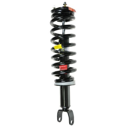
Here we have our old part from the vehicle and our new part from 1AAuto.com. As you could see, we have the same strut mounts up top, same spring, same strut assembly, same amount at the bottom. The only thing that's different is that it's up top here. We have a spacer for the lift and level on our truck. That just means that it makes the front of the truck sit a little bit higher so we can clear those big wheels and tires. This simply unbolts, bolts over to our new quick strut assembly, and bolts right back into the vehicle. This means that our new part comes complete with the spring already installed under the new strut mount onto our new strut assembly.
Now you don't have to worry about the headache and high risk of using a spring compressor at home. Simply remove your old part, and install your new one, just like factory.
We've placed our strut spring assembly into a vise so we can remove the three 15 millimeter nuts holding our leveling spacer onto the strut assembly. Start all of the nuts. We don't have a socket that can get in here, but if you do, the torque spec for these is 45 foot-pounds. Reinstall the strut.
Line up the bolts on the strut mount into the frame. Tighten the nuts on the top of the strut mount. Again, if you can get a torque wrench in there, it's going to be 45 foot-pounds on these nuts as well. Reinstall the bottom of the sway bar link into the control arm. Start the nut on the bottom of the lower sway bar link joint, counter hold the base of the lower joint with an 18 millimeter wrench. Tighten the nut with an 18 millimeter socket and ratchet.
You'll notice in the next few shots that the sway bar length is not connected in the video, despite us having just shown you the step to install it. You should be able to install your sway bar link after you've installed the strut and upper control arms, but in our case our vehicle is lifted, and we went through a few steps before realizing we had the incorrect sway bar link, meaning we had to go back a few steps in order to install it.
We're inserting a pry bar into the slot of the lower control arm so we can pry the strut over to the bushing. Install the punch. Hammer the punch in to help line up. Line up the bolt hole by manipulating the punch. Once you're in a good ways and the threads are inside the sleeve and lined up, you may need a pry bar to help line the back of the strut up. Finish tapping the bolt through.
Start the nut by hand. Don't tighten the bolt fully until the load of the vehicle is on the suspension. Line up the splines on the axle. Put the splines in the hub. Once it's started, we're just going to install the axle nut by hand to keep it in place while we line up the rest of our suspension.
Reinstall the upper bolt joint into the spindle. Tighten it with a 22 millimeter socket and ratchet. Torque the upper control arm nut to 40 foot-pounds. Add an additional 90 degrees.
Reinstall the harness into the keepers on the bottom of the control arm. Reinstall the connector. Push down on the safety tab. We're going to use a screw jack to put load on the suspension because we're on a lift. If you're doing this from a jack and jack stands you can use a floor jack. Torque the bottom strut bolt to 155 foot-pounds. You can now release the load from your suspension.
Reinstall the rotor onto the hub. Make sure that you don't twist the line on your brake hose. Reinstall the caliper carrier assembly onto the rotor, and start the bolts on the back side. Tighten the bolts down with a 21 millimeter socket and ratchet. Torque the caliper bolts to 130 foot-pounds.
Reinstall your wheel and tire onto the vehicle. Start the lug nuts with a 22 millimeter socket. Get all the lug nuts as tight as you can in the air. Then lower the vehicle. After tightening your axle nut, torque it to 185 foot-pounds. Pop the center cap back into place. Torque your lug nuts to 135 foot-pounds in a cross pattern.
Thanks for tuning in. We hope this video helped you out. Next time you need parts for your car, please visit 1AAuto.com. Also check out our other helpful how-to and diagnosis videos.
Shop Products


How to Replace Strut Assembly 2000-05 Ford Focus
Watch this video to learn how to fix a sagging or loose suspension. The experts at 1A Auto show how to replace the front shocks in your 00-05 Ford Focus.
