How to Replace Lower Ball Joints 2002-08 Dodge Ram 1500
Created on: 2016-07-25
Watch this video to learn how to replace a worn out or torn ball joint on your 02-08 Dodge Ram truck.
-
step 1 :Removing the Wheel
- Loosen the 22mm lug nuts with the vehicle on the ground
- Pry out the center cap with a pick
- Loosen the 35mm axle nut
- Raise the vehicle with a floor jack
- Secure the vehicle on jack stands
- Remove the lug nuts
- Pull off the wheel
-
step 2 :Removing the Rotor and Axle Nut
- Remove the two 21mm bolts securing the caliper bracket to the spindle
- Tie the caliper assembly out of the way by hanging it from the frame
- Remove the rotor
- Remove the axle nut
-
step 3 :Removing the Tie Rod
- Tap the end of the axle to push it out of the hub
- Remove the 21mm nut from the tie rod until it's at the bottom
- Tap the bottom with a hammer
- Remove the 21mm nut the rest of the way
- Pull the tie rod up and out of the control arm
-
step 4 :Removing the Spindle from the Control Arm
- Loosen the 22mm nut connecting the upper ball joint to the spindle
- Tap the front of the knuckle with a hammer without cracking it
- Once loose, hit the bottom of the control arm to release the joint from the knuckle if needed
- Release the tab on the connector for the ABS sensor
- Disconnect the ABS sensor
- Release it from the clamps under the control arm
- Remove the axle shaft from the wheel bearing
-
step 5 :Removing the Spindle
- Pinch the cotter pin legs out straight and together
- Twist the cotter pin out of the castle nut
- Remove the 22mm castle nut with a 22mm socket and breaker bar
- Place weight onto the top of the spindle
- Hit the bottom of the spindle behind the ball joint to release it
- Remove the Spindle
-
step 6 :Removing the Lower Ball Joint
- Release the snap ring on the top of the ball joint with snap ring pliers
- Place the receiving tube from the ball joint press onto the lower end of the ball joint
- Install a cup onto the top of the press
- Tighten down the press with a 22mm socket and breaker bar
- Remove the grease fitting with an 8mm socket
- Place the tube onto the bottom of the ball joint
- Reinstall the press
- Insert the thread onto the top center of the ball joint
- Press the ball joint out
-
step 7 :Reinstalling the Lower Ball Joint
- Install the ball joint into an installation cup
- Install the joint into the spindle with a cup on top
- Let the ball joint bottom out
- Tighten the joint until seated fully into the lower control arm with a 22mm socket
- Remove the ball joint press
- Spread the snap ring with snap ring pliers
- Insert the snap ring into place
- Install the grease fitting with a 10mm wrench in a direction that won't interfere with the spindle (backwards or forwards)
-
step 8 :Reinstalling the Spindle
- Insert the lower ball joint and axle into the spindle
- Thread the castle nut on
- Install the axle splines into the hub
- Hand tighten the axle nut
- Slide the upper ball joint into the spindle
- Tighten the 22mm upper ball joint nut
- Torque the 22mm upper ball join nut to 40 foot-pounds and add an additional 90 degrees
- Torque the 22mm lower ball join nut to 38 foot-pounds and add an additional 90 degrees
- Insert the cotter pin vertically into the castle nut
- Bend the longer leg down and over
- Leave the short leg intact or snip it off with pliers
-
step 9 :Reinstalling the Tie Rod
- Insert the tie rod into the spindle
- Start the nut by hand
- Tighten the 21mm nut with a socket and ratchet
- Torque the tie rod nut to 45 foot-pounds
-
step 10 :Reinstalling the Rotor and Caliper
- Insert the wiring harness into the keepers on the control arm
- Reconnect the connector
- Insert the rotor into place
- Insert the caliper to the rotor
- Tighten the 21mm bolts to the caliper
- Torque the caliper bolts to 130 foot-pounds
-
step 11 :Reattaching the Wheel
- Slide the wheel into place
- Start the lug nuts by hand
- Tighten the lug nuts preliminarily
- Lower the vehicle to the ground
- Tighten the axle nut
- Torque the axle nut to 185 foot-pounds
- Replace the center cap
- Tighten the lug nuts to 135 foot-pounds in a crossing or star pattern
Tools needed
-
35mm Socket
Socket Extensions
Torque Wrench
Hammer
Ball Joint Press
Pry Bar
Jack Stands
Small Hook
21mm Socket
Flat Blade Screwdriver
Snap Ring Pliers
8mm Socket
Bungee Cord
Ratchet
Floor Jack
Needle nose pliers
1/2 Inch Breaker Bar
22mm Socket
Brought to you by 1AAuto.com, your source for quality replacement parts and the best service on the Internet.
Hi, I'm Mike from 1A Auto. I hope this how-to video helps you out, and next time you need parts for your vehicle, think of 1AAuto.com. Thanks.
In this video, we're going to show you how to replace the lower ball joints in this Dodge Ram. This one is a 2008, but the procedure is pretty much the same for 2006 to 2008 1500 Dodge Rams. We do this on the passenger side, but the driver's side is the same procedure.
You'll need new ball joints from 1AAuto.com, 8 to 35 millimeter sockets with a ratchet and extensions, a breaker bar, hooked picked, bungee cords or mechanics wire, pry bar, hammer, flat blade screwdriver, needle nose pliers, snap ring pliers, ball joint press, torque wrench, and jack and jack stands.
With the vehicle on the ground, using the 22 millimeter socket and breaker bar, break the lug nuts for your wheel loose. These chrome lug nuts tend to be swollen, so make sure your socket's on there good. Using the small pick, remove the center cap from the wheel. Using a 35 millimeter socket and a breaker bar crack the axle nut loose. Raise and support your vehicle. Finish removing the lug nuts. Remove the wheel and tire from the hub.
Remove the two 21 millimeter bolts securing the caliper bracket to the spindle. Be sure to crack both of these loose before removing them. If they are removed fully one at a time, the caliper can twist and cause the flex hose on the brake line to tear. Be sure to support the assembly while you remove the last bolt. Remove the entire caliper and carrier assembly. Using a bungee cord secure it out of the way by hanging it off of the frame. Remove the rotor from the hub.
Brace the hub with a pry bar and finish removing your axle nut. Using a hammer, tap the end of the axle to push it out of the hub. Remove the nut for the tire rod. Take a 21 millimeter socket and ratchet. You want to leave the nut on a few threads so that it's flush with the bottom of the stud. Carefully tap up with a hammer. Remove the nut. Remove the tie rod from the control arm. Remove the 22 millimeter nut connecting the upper ball joint to the spindle.
Tap the front of the knuckle right where the ball joint comes through with a hammer to release it, careful not to hit it too hard because this is aluminum and it could crack. Once it's loosened up, you may have to hit the bottom of the control arm to release the joint from the knuckle. Using a flat blade screwdriver, release the tab on the connector for the ABS sensor. Push down and release the connector. Release it from the clamps under the control arm.
Pull down on the spindle or push up on the upper control arm to separate them and remove the axle shaft from the wheel bearing.
With a pair of needle nose pliers, straighten out the legs on the cotter pin. You want to get them as tight as you can, and as free of kinks as possible. This may mean pinching them together, and working them back and forth a little. Keep them together. Stick one of the legs from your pliers through the eyelet of the cotter pin. Clamp down, and twist it out. Regardless of whether or not the cotter pin comes out in one piece, you will want to replace these after they've been removed.
Using a 22 millimeter socket and breaker bar, remove the nut on the lower ball joint. Ensure that your axle nut is partially installed so the hub—once released from the ball joint—does not fall. Put some weight onto the top of the spindle, either by pulling down with your hand or a pry bar, and hit the bottom of the spindle here with a hammer to release the ball joint from the spindle. Once the ball joint is separated from the spindle, remove your axle nut the rest of the way.
Release the axle from the hub and the spindle from the ball joint. Using a bungee cord, zip ties, or mechanics wire, secure your CV axle up and out of the way of your lower ball joint. Using a pair of normally closed snap ring pliers, release the snap ring on the top of the ball joint. Place the receiving tube onto the bottom of the lower ball joint. Set it onto your press. Install a cup onto the top of the press to protect the grease fitting and to keep the press centered.
Using a 22 millimeter socket and breaker bar, tighten down on the press until the ball joint is released from the control arm. We're going to use an 8 millimeter socket to remove the grease fitting in order to get the added clearance to finish pressing the joint out.
Now you'll put your tube back onto the bottom of the ball joint. Reinstall your press, and without a cup on the top, put the threaded end of the press directly onto the top center of the ball joint. Press it the rest of the way out. When the joint is close to coming out, hold the press if it's safe to do so. Remove the assembly from the control arm.
Here we have our old ball joint, which we removed from our truck, and our new ball joint from 1A Auto. As you can see, there are some minor aesthetic differences, but the taper and the diameter of the joint are exactly the same. Same spline, they have a nice new boot, this one on our vehicle had actually collapsed in some, which obviously isn't going to hold grease very well. It's all dried out and rusted inside—I can barely get this thing to move.
Our new ball joint comes with a new snap ring that will sit on top of the control arm, to keep from the vehicle moving up and down and from working the ball joint out of its seat; A 90 degree zerk fitting, which is actually going to be a lot easier to access inside the vehicle; A new castle nut; And a new cotter pin to secure it and keep it from turning out. When it comes time to remove this ball joint in the future, you'll see that we have a slot in there, which allows you to keep the ball joint in place with a flat blade screwdriver, while undoing this castle nut, making it easier to remove a stubborn old ball joint, whereas this one has no provision to keep it from spinning.
Install the ball joint into an installation cup that fits the rim of the joint as best you can. Install the joint into the spindle with the cup on top, which will allow the joint to come through until it bottoms out. Make sure it's in there nice and straight. Using a 22 millimeter socket and ratchet, tighten it down until the joint seats fully into the lower control arm. Once you can see that the ball joint is seated fully, all the way around the control arm, remove your ball joint press.
Use your snap ring pliers to spread the new snap ring. Install it into the groove of the ball joint. Be sure that it's fully seated in there. Install your zerk/grease fitting. Using a 10 millimeter socket, tighten down your grease/zerk fitting. Be sure to face it in a direction that won't be interfered with by the spindle, such as backwards or forwards, as long as you can do so without stripping it.
Install the ball joint as well as the CV axle into the spindle, making sure that both line up properly. Start the washer and castle nut onto the threads of the ball joint. Line up and install the spines of your axle into the hub. Start your axle nut on as far as it'll go. Lift up on the upper control arm, slide the upper ball joint into the spindle. Pull down until you're able to get the nut started onto the threads. Tighten it down with a 22 millimeter socket and ratchet. Torque the upper ball joint to 40 foot-pounds. Add an additional 90 degrees.
Reinstall the tie rod into the spindle. Start the nut. Tighten it with a 21 millimeter socket and ratchet. Torque the tie rod to 45 foot-pounds. Reinstall the harness into the keepers and the bottom of the control arm. Reinstall the connector.
Push down on the safety tab. Reinstall the rotor onto the hub. Make sure that you don't twist the line on your brake hose. Reinstall the caliper carrier assembly onto the rotor. Start the bolts on the back side. Tighten the bolts down with a 21 millimeter socket and ratchet. Torque the caliper bolts to 130 foot-pounds.
Reinstall your wheel and tire onto the vehicle. Start the lug nuts with a 22 millimeter socket. Get all the lug nuts as tight as you can in the air and lower the vehicle. After tightening your axle nut torque it to 185 foot-pounds. Pop the center cap back into place. Torque your lug nuts to 135 foot-pounds in a cross pattern.
Thanks for tuning in. We hope this video helped you out. Next time you need parts for your car, please visit 1AAuto.com. Also check out our other helpful how-to and diagnosis videos.
Shop Products


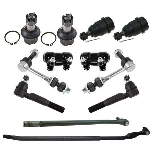
Dodge Ram 1500 2500 3500 Front 12 Piece Steering & Suspension Kit TRQ PSA73531
Part Details:
- (2) Front Sway Bar Links
- (1) Front Inner Drag Link
- 12 Piece
- (1) Front Pitman Arm to Steering Arm Tie Rod Adjusting Sleeve
- (2) Front Lower Ball Joints
- (2) Front Outer Tie Rods
- (1) Front Tie Rod Adjusting Sleeve
- (1) Front Inner Tie Rod at Pitman Arm
- (2) Front Upper Ball Joints

How to Replace Front Lower Ball Joint 2005-16 Toyota Rav4
How to replace a rusty, worn, or broken front lower ball joint on your 05-16 Toyota Rav4.
